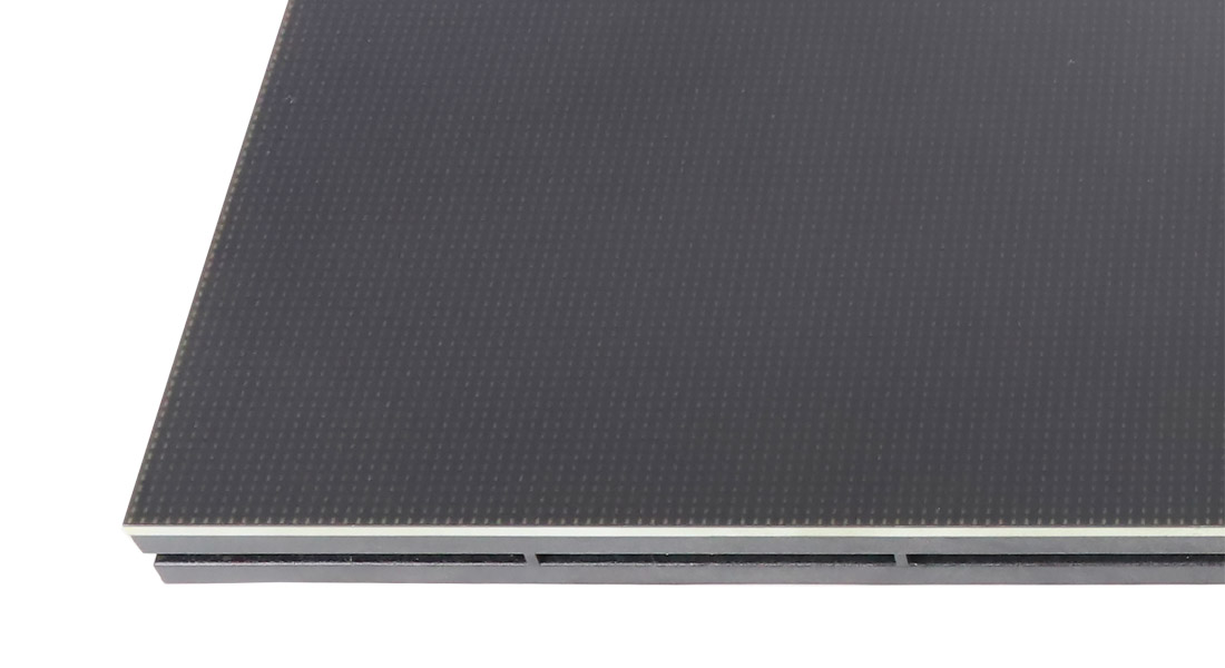
A module family for detailed indoor displays
EagerLED’s COB modules mount LED chips directly on a circuit board and encapsulate the surface. The manufacturer describes these modules for indoor conference rooms, control rooms and studios where detailed content and short viewing distances matter. The source explains both front-mounted and flip-chip packaging, while the specification rows selected here identify flip-chip COB. COB module specifications.
COB is a packaging construction, not a complete screen size or resolution. A buyer still needs to select the module footprint, pixel matrix and compatible cabinet and control system. This page compares documented choices at P0.62, P0.78, P0.93, P1.25 and P1.53. It keeps each pitch attached to the footprint where the source confirms it.
Use the LED module category when the task is module integration or replacement. If the project requires a complete shallow indoor wall, the EA600COB3 provides a cabinet-level reference with its own dimensions and electrical data. A module proposal and an assembled-wall proposal have different scopes.
The footprint changes the pixel matrix
The selected source rows belong to two module families. The 320 × 160 mm entries below list 600-nit brightness. The 150 × 168.75 mm entries list a 500–800-nit range. Every selected row lists 3840 Hz refresh. COB variant tables.
| Module footprint | Pitch | Module resolution | Driving duty | Listed brightness |
|---|---|---|---|---|
| 320 × 160 mm | P1.25 | 256 × 128 pixels | 1/64 | 600 nits |
| 320 × 160 mm | P1.53 | 208 × 104 pixels | 1/52 | 600 nits |
| 150 × 168.75 mm | P0.62 | 242 × 272 pixels | 1/64 | 500–800 nits |
| 150 × 168.75 mm | P0.78 | 192 × 216 pixels | 1/64 | 500–800 nits |
| 150 × 168.75 mm | P0.93 | 160 × 180 pixels | 1/60 | 500–800 nits |
| 150 × 168.75 mm | P1.25 | 120 × 135 pixels | 1/60 | 500–800 nits |
P1.25 therefore has two different size and matrix combinations in this comparison. Neither should replace the other in a drawing or spare order. The P1.53 entry shown here belongs to the 320 × 160 mm family; this table does not assign that pitch to the other footprint.
The P0.62 source row requires care. Its published 242 × 272 matrix is not exactly proportional to the 150 × 168.75 mm physical footprint. Ask the supplier for a confirmed module drawing and pixel map before deriving a native-resolution target from that row. Retain the manufacturer’s nominal label rather than silently changing it to a value calculated from a rounded pitch. COB module matrices.
Brightness also needs configuration confirmation. The 500–800-nit entry describes the listed range for those module rows. Request the intended operating point and associated control settings. A demonstration at one brightness does not establish the behavior of the supplied system throughout that range. COB brightness entries.
Work backward from the content matrix
Fine pitch is useful when the selected wall needs enough pixels for small text, diagrams or several simultaneous windows. Set the required pixel canvas before assuming that a physical wall size can display it natively. Module count, footprint and pixel matrix must agree.
The examples below use the verified 150 × 168.75 mm matrices in the source. They calculate a 3840 × 2160-pixel canvas using whole modules. They are module-layout arithmetic, not approved cabinet designs or complete bills of materials. COB module matrices.
| Selected module | Calculated grid, across × up | Module count | Calculated image size |
|---|---|---|---|
| P0.78, 192 × 216 pixels | 20 × 10 | 200 | 3000 × 1687.5 mm |
| P0.93, 160 × 180 pixels | 24 × 12 | 288 | 3600 × 2025 mm |
| P1.25, 120 × 135 pixels | 32 × 16 | 512 | 4800 × 2700 mm |
The physical size grows as the selected matrix contains fewer pixels per module. The integrator must still show that the desired grid fits its cabinet arrangement and provide the controller capacity, power distribution and service method. A module layout that works arithmetically may not correspond to a standard cabinet grid.
For a fixed room opening, the process may run in the other direction. Determine which whole modules fit, calculate the actual canvas and then decide how the source content will be scaled. Review the smallest meaningful text in the ordinary application, not just a test image made to suit the screen.
Surface appearance and acceptance
The source describes a smooth, hardened encapsulated surface and a 140° viewing-angle feature. Evaluate a sample under the room’s actual lighting and from the intended seats. Surface reflections, low-brightness gradients and small lettering deserve attention alongside a vivid full-screen video. COB surface description.
For a control room or presentation area, prepare a small set of acceptance content: the normal desktop arrangement, a detailed diagram and uniform fields that reveal visible differences between modules. Agree the operating brightness for that review. If cameras will record the screen, test the intended camera settings with the delivered configuration.
The manufacturer’s surface-protection language does not provide an outdoor enclosure rating for these indoor module families. Obtain the approved cleaning method and environmental limits for the exact module. Avoid turning general moisture resistance into a promise that the rear connections or a custom cabinet can tolerate exposure.
The GOB module family describes a different construction, with a protective layer over packaged LEDs. Comparing COB and GOB should include the exact pitch, footprint and complete display configuration rather than treating the names as two interchangeable coatings.
Integration and service planning
| Project condition | COB module decision | Confirm with the integrator |
|---|---|---|
| A native high-resolution canvas | Choose a verified module matrix | Whole-module and cabinet grids, controller map and physical size |
| An existing cabinet needs repair | Match the precise footprint and row | Connectors, scan duty, retention and configuration files |
| Close viewing in a bright room | Review the chosen surface and brightness | Sample appearance with normal content and room lighting |
| A recessed installation | Establish how modules leave the assembly | Front or rear access, tools and clearance |
| Long-term replacement planning | Specify matching spare modules | Calibration information and the approved replacement procedure |
Module-level packaging does not establish front service for every possible cabinet. Request the removal sequence for the assembly you are buying. Check access to the first module and to its connectors after surrounding trim is installed. Store spare modules using the supplier’s handling instructions and label them with the screen configuration they belong to.
The EA640F2 offers another cabinet-level comparison with separate SMD/GOB and COB choices. Keep the complete product designation on the order; identical nominal pitch and dimensions are insufficient evidence that modules from different families share the same interface.
COB module questions
Does COB mean the finished screen is 4K?
No. The module matrix and assembled grid determine native resolution. The example layouts above calculate 3840 × 2160 pixels, but their cabinet and control arrangements still need approval. COB module matrices.
Can either P1.25 module fit the same cabinet?
The two documented footprints and pixel matrices differ. Use the cabinet’s approved module specification and verify mounting, connections and control settings.
Is P1.53 listed in both footprints?
The confirmed P1.53 row in this comparison is 320 × 160 mm with 208 × 104 pixels. Do not transfer it to the 150 × 168.75 mm family without separate source evidence. COB variant tables.
Does the smooth surface make service unnecessary?
The encapsulated surface changes the construction, but modules and system components still need an accessible replacement procedure. Specify tools, spares and configuration records with the complete installation.
What information should accompany an inquiry?
Send the desired pixel canvas or available physical size, normal content and viewing positions through the module quote request. Identify the footprint and pitch being considered, and ask for a complete matched electrical and mechanical specification.
CHECK THE DETAILS
Sources & references
Source pages can change. Access dates record when they were consulted.
- COB module specifications Accessed 28 September 2026
Discuss COB LED module family for your project.
Share the application, destination and screen dimensions to request a configuration and written quotation.
Request a project quote